www.samuelprof.com

DIGITAL ELECTRONICS


Analog-to-Digital Conversion

This is a sample of the large number of analog-to-digital conversion methods. The basic principle of operation is to use the comparator principle to determine whether or not to turn on a particular bit of the binary number output. It is typical for an ADC to use a digital-to-analog converter (DAC) to determine one of the inputs to the comparator.

Digital-Ramp ADC Successive Approximation ADC Flash ADC
Index

Electronics concepts

Digital Circuits
 
HyperPhysics*****Electricity and magnetism R Nave
Go Back


Digital Ramp ADC

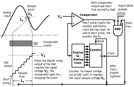
Conversion from analog to digital form inherently involves comparator action where the value of the analog voltage at some point in time is compared with some standard. A common way to do that is to apply the analog voltage to one terminal of a comparator and trigger a binary counter which drives a DAC. The output of the DAC is applied to the other terminal of the comparator. Since the output of the DAC is increasing with the counter, it will trigger the comparator at some point when its voltage exceeds the analog input. The transition of the comparator stops the binary counter, which at that point holds the digital value corresponding to the analog voltage.

Analog-to-Digital Converters
Index

Electronics concepts

Digital Circuits

Reference
Tocci
Digital Systems, Sec 10-8.
 
HyperPhysics*****Electricity and magnetism R Nave
Go Back


Successive Approximation ADC

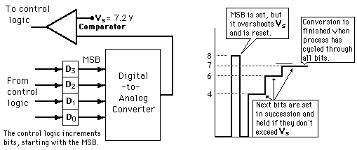
Illustration of 4-bit SAC with 1 volt step size (after Tocci, Digital Systems).

The successive approximation ADC is much faster than the digital ramp ADC because it uses digital logic to converge on the value closest to the input voltage. A comparator and a DAC are used in the process.

Analog-to-Digital Converters Digital-to-Analog Converters Comparator
Index

Electronics concepts

Digital Circuits

Reference
Tocci
Digital Systems, Sec 10-10.
 
HyperPhysics*****Electricity and magnetism R Nave
Go Back


Flash ADC

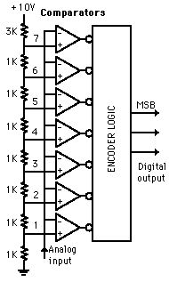
Illustrated is a 3-bit flash ADC with resolution 1 volt (after Tocci). The resistor net and comparators provide an input to the combinational logic circuit, so the conversion time is just the propagation delay through the network - it is not limited by the clock rate or some convergence sequence. It is the fastest type of ADC available, but requires a comparator for each value of output (63 for 6-bit, 255 for 8-bit, etc.) Such ADCs are available in IC form up to 8-bit and 10-bit flash ADCs (1023 comparators) are planned. The encoder logic executes a truth table to convert the ladder of inputs to the binary number output.

Analog-to-Digital Converters
Index

Electronics concepts

Digital Circuits

Reference
Tocci
Digital Systems, Sec 10-11.
 
HyperPhysics*****Electricity and magnetism R Nave
Go Back


Home | MDG CLUB MEMBER LIST | mach & power.com | control system 11 | control system 3 | ELECTROMAGNETIC FIELD THEORY | ELECTROMAGNETIC FIELD THEORY 3 | TUTOR ON ELECTROSTASTISIC | electromagnetics | CONTROL ENGINEERING SYSTEM 1 | continuation of control system 1 | control system 2 | ELECTROMAGMETIC FIELD THEORY 4 | ELECTROMAGNETIC FIELD THEORY | THE ONE | teleccom | tele | CIRCUIT ANALYSIS | CONTROL | CONTROL | DIGITAL ELECTRONICS | mail me. | my serch engent | ENGINEERING ASPECT OF LIFE | QUOTE ME.COM | About Me | Family Photo Album | My Pets | Vacation Photo Album | CONTACT ME

Pulsed Power Thyristors (SCRs) and Assemblies


The PT family of Pulsed Power Thyristors (PPTs) are based on Dynex’s GTO technology and are designed for long term stability under D.C. voltages and have structures that are resistant to cosmic ray induced failures at normal working voltages.

Dynex’s Pulsed Power thyristors may be used to connect a source of stored energy, such as a capacitor to a load, or to bypass and protect the load in the case of a crowbar circuit. In these pulsed power applications where the rate of rise of current is very fast, the pulse power switch is acting as a closing switch and ordinary phase control thyristors (SCRS) are likely to fail due to the high di/dt experienced.

Pulsed Power Thyristors may also be required to act in the opening switch mode as well. Such applications may include those where voltage is reapplied to the pulse power switch shortly after closing and the switch needs to have recovered blocking capability or the transferred energy needs to be controlled. In these applications, the switch needs to have turn-off capability to reduce the natural turn-off time (tq) of the device. The device is operated in GTO mode with the appropriate commutating gate drive.


Enter supporting content here