|
www.samuelprof.com |
|
control system 2
|
|
Block diagram and layout
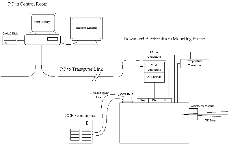
A simplified block diagram showing the major components of the system is given in Layout 1. The system is in two parts:
the camera and electronics at the telescope, and the instrument computer and display system in a remote control room. The
telescope end includes all necessary electronics to operate the arrays, convert the analog outputs to digital data and co-add
images. A motor control unit and a temperature control system are all packaged alongside the camera itself, with the entire
assembly held in a frame which supports the instrument on the telescope and during handling. Observers interact with the camera
system at the keyboard of a 486-based PC located in a remote control room. Images from one or both channels can be manipulated
and displayed on a second screen. The two channels may be referenced as either "fast/slow" when discussing electronics, or
as "long/short" when discussing the wavelength ranges.
Layout 1: A block diagram of the UCLA 2-channel infrared camera system |
